
Medical Device Prototype Development: From Software Design to Regulatory Testing
I’m not going to lie, a lot of the projects we do at Scythe Studio are related to the medical […]

Join us at Qt C++ Warsaw Meetup - 21.08.2025
Sign up for free!
Technical managers in the embedded space often face a classic challenge: integrating industrial communication protocols into modern applications. One such ubiquitous protocol is Modbus, a stalwart in industrial automation.
In this article, we’ll explore how Qt simplifies Modbus integration, offering cross-platform support and powerful tools like QModbusClient and QModbusServer—if you’re looking for expertise in embedded systems development, our Qt/C++ skills can help you streamline your projects.
Modbus is a serial communication protocol originally developed by Modicon (Schneider Electric) in 1979 for PLC (Programmable Logic Controller) systems.
Thanks to its simplicity and openness, Modbus quickly became a de facto standard in industrial communication. It’s an openly published and royalty-free protocol, meaning any vendor can implement it on their devices.
Over the decades, Modbus has been widely adopted in SCADA systems, factory automation, power systems, and many other industrial domains as a common language for connecting electronic devices, enabling reliable communication across multiple devices in industrial environments.
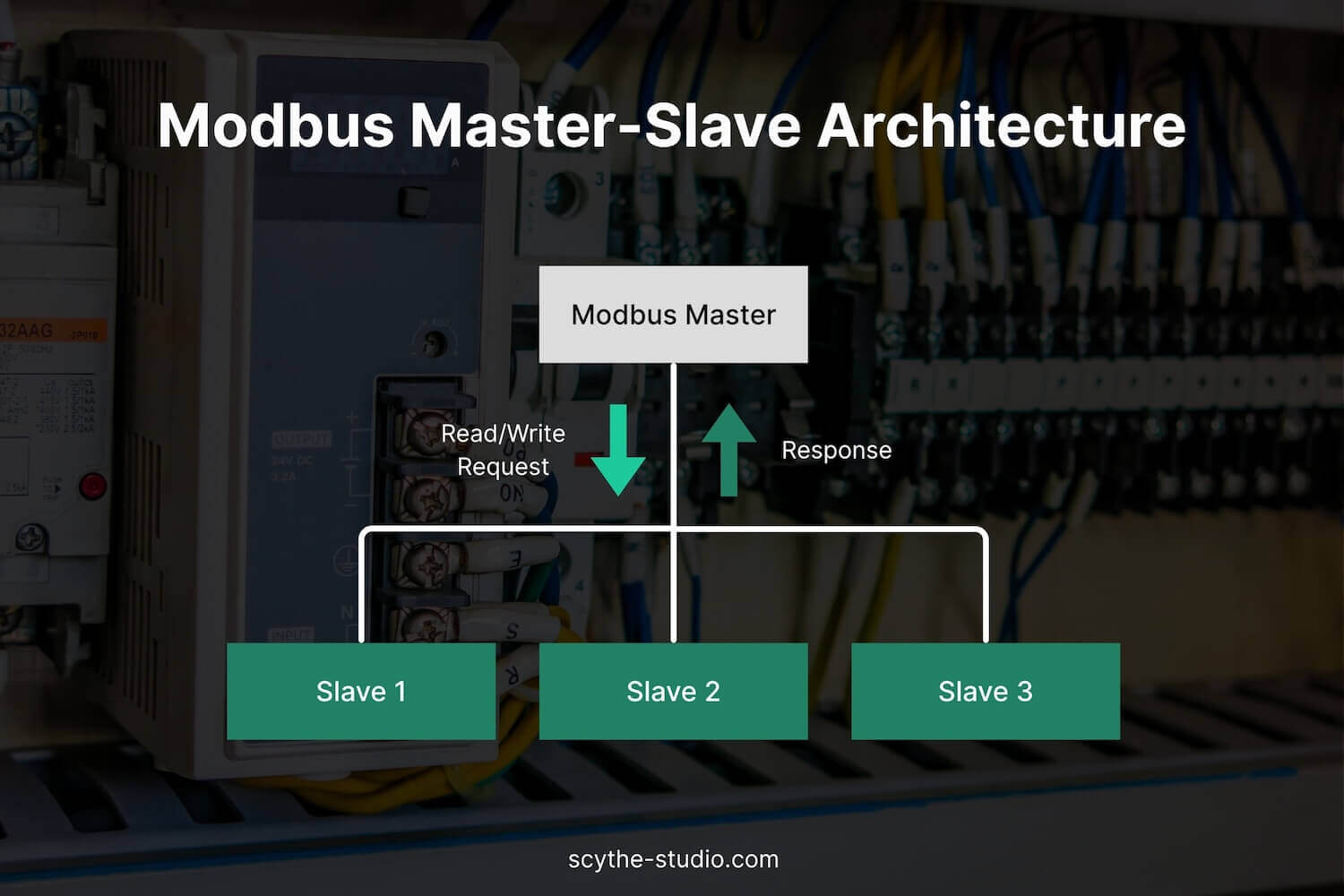
At its core, Modbus uses a simple request-reply message structure. It follows a master/slave (client/server) model: a single master device (e.g., an HMI or central controller) polls one or more slave devices (sensors, actuators, PLCs) in turn.
The master sends a request (such as “read register X” or “write value Y to coil Z”), and the addressed slave responds with the requested data or an acknowledgment. Slaves do not speak unless spoken to (they only send data when replying to the master), which simplifies the communication process. A Modbus master can manage up to 247 slaves on one serial network, each identified by a unit address. This polled communication loop is straightforward and ensures only one device talks at a time on the bus.
Each Modbus device organizes its data in a set of tables holding coils (binary outputs), discrete inputs (binary inputs), holding registers (16-bit output registers), and input registers (16-bit input readings).
For example, a temperature sensor might expose the current temperature in a holding register, which the master can read, or a PLC might have coils that the master can turn on/off. Modbus functions (identified by function codes in the message) allow reading and writing these data points. The protocol moves raw bits and words with minimal formatting, which ensures efficient data exchange.
This simplicity is one of Modbus’s key strengths – it’s often possible to implement basic Modbus support on a microcontroller in a matter of a day. By combining data from multiple registers, systems can enable advanced data acquisition and supervisory control processes. Modbus defines a clear set of rules for organizing and transmitting data types, such as coils and registers. Devices often share the same memory range for the registers, making communication and data management more efficient. The register address specifies where particular data is stored in this memory. This is part of the Modbus serial protocol, which defines how data is transmitted in a serial format.
Modbus messages include an , a data payload, and error-checking fields. A Modbus RTU message consists of several key components, including the address, function code, and data field, ensuring clear data communication.
In serial Modbus (RTU/ASCII), a cyclic redundancy check (CRC or LRC) is used for error detection, while on TCP/IP, the network’s own error-checking mechanisms (such as the Internet Protocol’s built-in checksums) are used. The uncomplicated frame structure makes Modbus easy to parse and generate, even on resource-constrained devices.
When transmitting data, it’s crucial to handle the byte count correctly to ensure the accuracy of the data exchange. This is where the data byte comes in, defining the actual size of data being transferred.
Modbus exists in a few primary variants, all sharing the same basic data model and function set, but using different transport formats:
The most common form of Modbus, RTU frames are a compact binary format sent over serial lines (RS-485 or RS-232). Each 8-bit byte in a message can contain two 4-bit hex values (0–255), making RTU efficient in bandwidth. Messages start with a silent interval and are framed by timing (gaps between messages). An RTU message includes a 16-bit CRC (Cyclic Redundancy Check) for error detection at the end.
Modbus RTU is known for its efficiency and is widely used for its fast, compact communication. It’s well-suited to microcontrollers and field-bus networks and remains extremely popular in industrial devices that communicate over multi-drop RS-485 networks. With Modbus RTU, multiple coils or physical output registers can be controlled or read. The Modbus RTU protocol is well-suited for low-latency applications and data transmissions in industrial environments. The remote terminal unit (RTU) plays a key role in Modbus RTU by initiating communication and collecting data across remote devices. Additionally, Modbus RTU uses a protocol data unit (PDU) for the data exchange between master and slave devices.
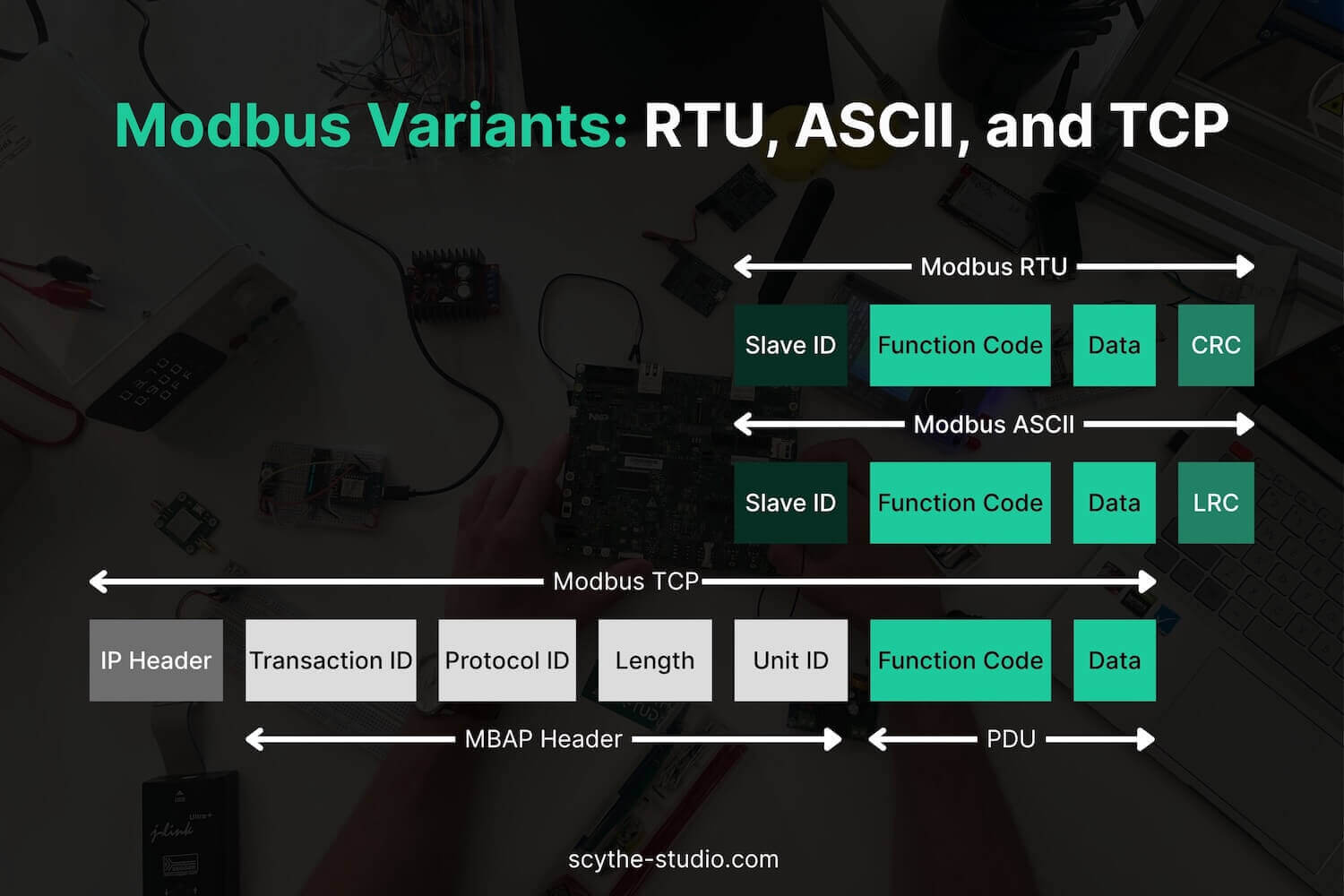
An alternative serial format where messages are encoded in ASCII text (readable characters). Each byte of data is sent as two ASCII characters (hexadecimal representation), and messages are delimited by a “:`” at the start and CR/LF at the end. Instead of a CRC, Modbus ASCII uses an LRC (Longitudinal Redundancy Check) for error checking.
ASCII mode is human-readable, but it doubles the message length and is far less efficient than RTU, transmitting only half the data at the same baud rate. Due to its lower performance, Modbus ASCII today sees little use – typically only in legacy systems or constrained channels that can’t reliably handle binary data.
A newer variant designed for Ethernet networks. Modbus TCP encapsulates Modbus messages within TCP/IP packets, using a special 7-byte MBAP header instead of the CRC used in serial modes. This header includes fields like a transaction identifier, protocol identifier, length, and a unit identifier (which serves the function of the slave address).
Modbus TCP typically uses port 502 and offers much higher speed plus the ability to have multiple devices communicate over the same network. It enables efficient data transmission across Internet Protocol (IP) networks and is ideal for integrating PLCs and controllers into plant networks, SCADA systems, or IIoT cloud systems. This variant also facilitates Modbus application protocol over the network.
The table below summarizes the key differences between Modbus RTU, ASCII, and TCP:
| Variant | Transport Medium | Data Encoding | Error Check | Typical Use Case |
|---|---|---|---|---|
| Modbus RTU | Serial (RS-485 or RS-232) | Binary frame (8-bit data) | CRC-16 (2 bytes) | High-efficiency on local serial networks; ideal for PLCs, sensors, and other devices on an RS-485 multi-drop bus. One master polls up to 247 slaves; robust and minimal overhead for real-time control. |
| Modbus ASCII | Serial (RS-232/RS-485) | ASCII characters (hex text) | LRC (1 byte) | Legacy scenarios where text format is needed or very simple devices. Human-readable but half the throughput of RTU at the same baud rate; rarely used in modern systems due to inefficiency and weaker error check. |
| Modbus TCP | Ethernet (TCP/IP network) | Binary protocol over TCP | TCP/IP (network-layer CRC) | Modern IP-based networks (LAN/WAN). Great for SCADA, HMIs, and connecting remote devices over Ethernet. No dedicated master—multiple clients can query a server. Requires networking infrastructure but allows long-distance and high-speed communication, with standard port 502. |
As you may already know, the Qt framework provides robust libraries for implementing various communication protocols. Modbus is no exception.
Qt’s SerialBus module (introduced in Qt 5.8) includes high-level classes for Modbus communication, making it straightforward to integrate Modbus into your application.
Whether you need to interface with a Modbus RTU device over a serial port or communicate with a Modbus TCP server over Ethernet, Qt has you covered with a unified API that can greatly simplify development and improve portability.
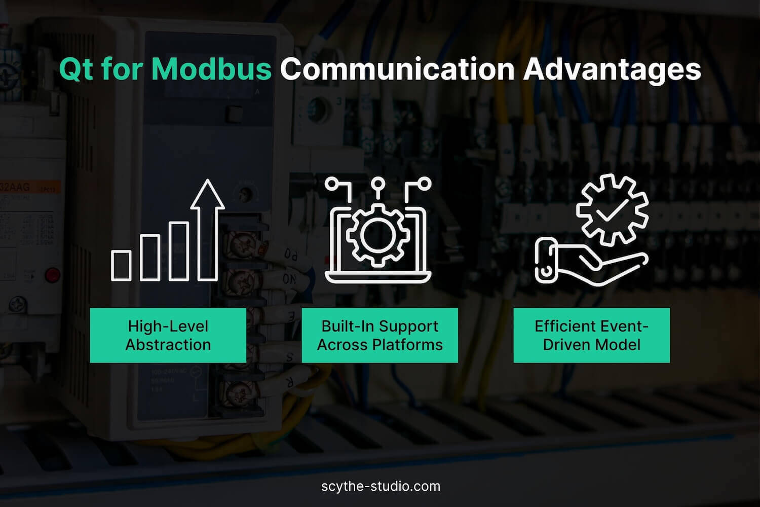
Apart from the general benefits of Qt (cross-platform support, rich C++ framework, modern UI tools – yes, Qt/ C++ development is one of our core specialties), there are three main advantages when using Qt for Modbus:
Qt provides an intuitive, high-level API for Modbus, so you avoid dealing with low-level serial bytes, socket programming, or manual frame assembly. Instead of writing a custom Modbus parser or using OS-specific serial-port calls, you can use Qt’s classes to open a connection and issue read/write requests with a few function calls.
Qt’s QModbusClient class, for example, lets you send a read request and handles formatting the Modbus PDU/ADU under the hood. The library takes care of inserting addresses, CRC calculations, timing between messages, and even splitting binary data types automatically. Qt also supports protocol implementation for both RTU and TCP variants, making it versatile for different industrial needs.
As a result, developers can focus on what data to exchange rather than how to encode it, which speeds up development and reduces bugs.
The Qt SerialBus module comes with out-of-the-box support for Modbus in both serial and TCP forms, so you don’t need separate libraries for different operating systems or Modbus variants. For example, the same Qt Modbus code can run on an embedded Linux board or a Windows PC—Qt uses the appropriate backend (serial-port API or TCP sockets) internally.
Qt provides specific classes such as QModbusRtuSerialMaster (for Modbus RTU over serial) and QModbusTcpClient (for Modbus over TCP/IP) to cover each transport mode; likewise, it offers QModbusRtuSerialSlave and QModbusTcpServer for implementing your own Modbus devices on serial or network interfaces. This unified framework means you can develop and test on one platform and deploy on another with minimal changes, while device identification remains efficient thanks to Qt’s native handling of multiple transport protocols.
Qt’s signal-slot mechanism is a perfect match for Modbus applications that require responsive, asynchronous communication. Rather than writing loops to poll for incoming data or block on responses, your application can react to Modbus events. For example, when you send a request using QModbusClient, the library returns immediately with a QModbusReply object; the actual response will arrive asynchronously. You can connect the reply’s finished signal to a slot (or lambda) in your code—Qt will invoke your handler as soon as the Modbus reply is received.
This non-blocking, event-driven design keeps the UI (or main loop) fluid and greatly simplifies thread management, while still allowing real-time reactions on the server side via signals like dataWritten. The result is cleaner code—no manual polling or flag checking—and perfect alignment with Qt’s architecture for GUI responsiveness and concurrent I/O.
Qt’s SerialBus module offers a range of classes to implement Modbus clients or servers easily in C++. Here are some of the key classes and their roles:
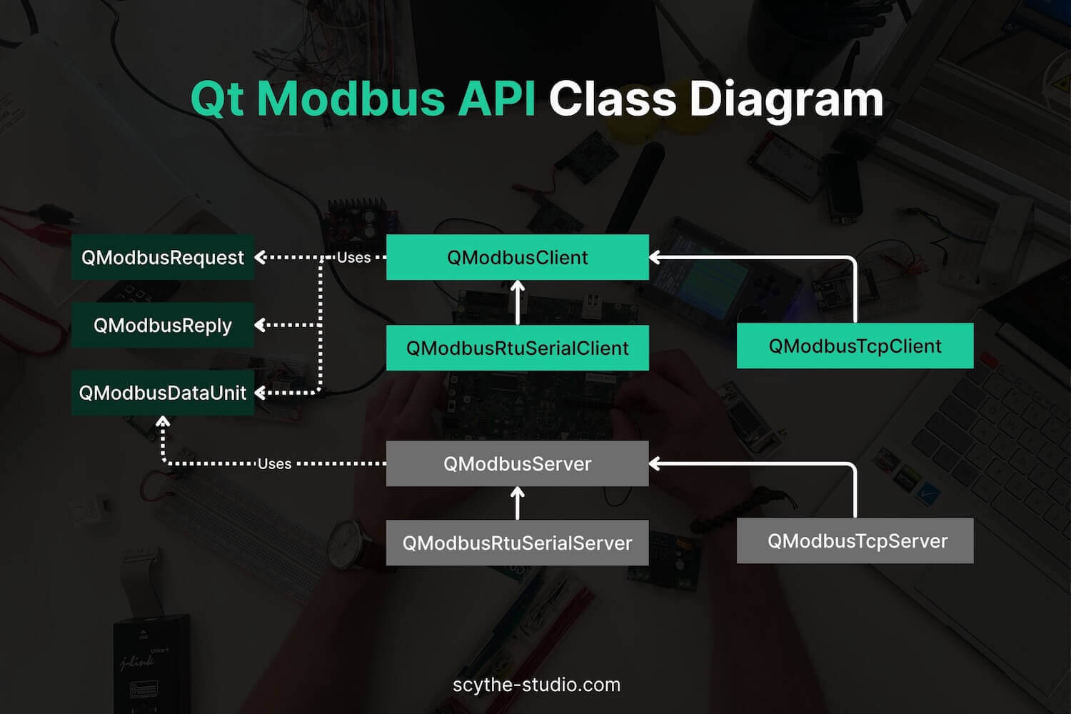
These Qt classes work together to simplify Modbus communications. Under the hood, Qt takes care of opening serial ports (via QSerialPort) or sockets (QTcpSocket), formatting messages, timing, and thread safety.
By using Qt’s Modbus API, an embedded developer can implement complex Modbus interactions with only a few dozen lines of high-level C++ code, all while remaining portable across Linux, Windows, or other Qt-supported platforms. It’s a powerful way to save development time and ensure reliability by leveraging Qt’s proven libraries.
In this example, we’ll create a Modbus TCP client and server that communicate over localhost (127.0.0.1) on port 50200. The server will hold 10 coils that the client can interact with by reading or writing data to them.
For the server, we’ll configure 10 coils that will be accessed via the client. The client will be able to read data from the server or write data to it.
To use Modbus in your Qt application, you’ll need the Qt Serial Bus Module. Before you begin, make sure that the Qt Serial Bus module is installed in your Qt environment. This module can be installed via the Qt Maintenance Tool. It’s located under Qt <Version> -> Additional Libraries.

First, let’s create the Modbus server. Thanks to QModbusTcpServer, this process is child’s play. We simply need to instantiate a QModbusTcpServer object and assign the necessary connection parameters.
Here’s how to set up the server:
server = new QModbusTcpServer(this);
const QUrl currentUrl = QUrl::fromUserInput("127.0.0.1:50200");
server->setConnectionParameter(QModbusDevice::SerialPortNameParameter, "Scythe Studio Modbus Server");
server->setConnectionParameter(QModbusDevice::NetworkPortParameter, currentUrl.port());
server->setConnectionParameter(QModbusDevice::NetworkAddressParameter, currentUrl.host());
server->setServerAddress(1);
Next, we need to define the data the Modbus server will hold. In our example, we want to set up 10 coils (NUM_COILS).
In Modbus, coils represent discrete values that can either be on (1) or off (0). These are typically used for controlling and monitoring things like switches or relays.
Here’s how you define it in the code:
QModbusDataUnitMap reg;
reg.insert(QModbusDataUnit::Coils, { QModbusDataUnit::Coils, 0, NUM_COILS });
server->setMap(reg);
Modbus data map (reg), which holds all the data units (like coils, registers, etc.) for the server. The server->setMap(reg) line applies this map to the Modbus server, configuring it to hold these 10 coils.
After that we’re ready to start the server.
if (!server->connectDevice()) {
	qDebug() << "Error with modbus connectDevice: " << server->errorString();
 }
And that’s it! Setting up the server is as easy as pie!
To connect the Modbus client to the server, we create a QModbusTcpClient object, configure the necessary properties, and then attempt to establish the connection using the following code:
// Create a Modbus client instance
m_modbusClient = new QModbusTcpClient(this);

// Define the server address and port
const QUrl currentUrl = QUrl::fromUserInput("127.0.0.1:50200");

// Set connection parameters
m_modbusClient->setConnectionParameter(QModbusDevice::NetworkAddressParameter, currentUrl.host());
m_modbusClient->setConnectionParameter(QModbusDevice::NetworkPortParameter, currentUrl.port());

// Try connecting to the server
if (!m_modbusClient->connectDevice()) {
    qCritical() << "Failed to connect to the server:" << m_modbusClient->errorString();
} else {
    qDebug() << "Successfully connected to the server.";
}
To write data to the Modbus server, we first create a Modbus data unit (writeUnit) to represent the coils we want to update. The unit starts at address 0 and contains the values from m_coils, which holds the coil states (either true or false).
QModbusDataUnit writeUnit = QModbusDataUnit(QModbusDataUnit::Coils, 0, NUM_COILS);
for (qsizetype i = 0, total = writeUnit.valueCount(); i < total; ++i) {
    writeUnit.setValue(i, m_coils.at(i));
}
Then, we send the write request using sendWriteRequest(). If the request is successful, we connect to the finished signal to handle the server's response:
if (auto *reply = m_modbusClient->sendWriteRequest(writeUnit, 1)) {
    if (!reply->isFinished()) {
        connect(reply, &QModbusReply::finished, this, [this, reply]() {
            if (reply->error() != QModbusDevice::NoError) {
                qDebug() << "Write error:" << reply->errorString();
            }
            reply->deleteLater();
        });
    } else {
        reply->deleteLater();  // Broadcast replies return immediately
    }
} else {
    qDebug() << "Write error:" << m_modbusClient->errorString();
}
To read data from the Modbus server, we initiate a read request for coils and process the response as follows:
// Request read operation for coils
if (auto *reply = m_modbusClient->sendReadRequest(QModbusDataUnit(QModbusDataUnit::Coils, 0, NUM_COILS), 1)) {
    if (!reply->isFinished()) {
        connect(reply, &QModbusReply::finished, this, [this]() {
            auto reply = qobject_cast(sender());
            if (!reply)
                return;

            // Check for errors in the response
            if (reply->error() == QModbusDevice::NoError) {
                qDebug() << reply->result().values();
                }
            } else {
                qDebug() << "Read response error:" << reply->errorString();
            }

            reply->deleteLater();
        });
    } else {
        delete reply; // Broadcast replies return immediately
    }
}
In the following demo video, you can see the complete process of how a Modbus TCP client interacts with a Modbus TCP server. The video demonstrates how the client connects to the server, sends a request to read coil values, and handles the server’s response.
Note: The Modbus response from the server always contains a 16-bit chunk, even if fewer coils are requested. This is because the Modbus protocol typically operates with 16-bit registers. In this example, the server responds with 16 coil values, but the client only writes 10 coils, starting from address 0.
Using Qt for Modbus integration in embedded systems offers significant value. You get the benefit of a high-level, cross-platform API that hides the complexity of bytes and protocols, while still delivering the performance and flexibility needed for industrial applications. Qt’s built-in Modbus support allows your applications to communicate with PLCs, sensors, and other field devices reliably – whether it’s over an old-school RS-485 line or a modern Ethernet network. The framework’s signal-slot model aligns perfectly with responsive, event-driven communication, resulting in clean and maintainable code.
From a project management perspective, Qt development can drastically cut down development and debugging time for Modbus features, and it provides the scalability to move from prototype to production on various hardware with minimal changes. This means faster time-to-market and lower long-term maintenance costs.
Need expert help bringing Modbus (or other industrial protocols) into your Qt project? Let’s talk.


Let's face it? It is a challenge to get top Qt QML developers on board. Help yourself and start the collaboration with Scythe Studio - real experts in Qt C++ framework.
Discover our capabilitiesI’m not going to lie, a lot of the projects we do at Scythe Studio are related to the medical […]

Trading software refers to the digital platforms and systems that enable investors and financial institutions to buy, sell, and manage […]

Verification and Validation (V&V) are two pillars that ensure a medical device is safe, effective, and compliant before it ever […]
