Secure Boot and Firmware Protection in Embedded Systems
Users of embedded devices – from industrial controllers to consumer electronics – are often unaware of hidden vulnerabilities that threaten […]

I welcome you to another blog post. The last one discussed a form of communication between devices using Qt Bluetooth Low Energy. I decided to stay on the topic of communication for a while longer, so in today’s post, we will discuss CAN Bus. This topic may be more difficult than the last but don’t worry—as usual, I will try to make it as simple and enjoyable as possible. Without further ado, let’s get started!
Let’s start ourselves with a little intellectual warm-up. Let’s say we have some vehicle including two ECUs (Electronic Control Units – in short, it’s a small embedded device that takes in input data from e.g. sensors, processes it, and sends it on). You want them to exchange information with each other, what is the easiest way to connect them? I’ll give you a few seconds to think…
Well, time’s up. The correct answer is a wire😅Simple yet effective! And if there are more ECUs? Again, you connect each one with a wire, and that’s it! This approach worked in the automotive industry until the 1980s. However, this solution had many drawbacks, so it was decided to come up with something smarter.
And so CAN Bus was created by Bosch company to address the growing complexity of electronic systems in vehicles. As cars became more advanced, manufacturers needed a way to connect various ECUs—such as those controlling the engine, transmission, brakes, and infotainment—without excessive wiring. Over time, the CAN bus became the standard outside automotive HMI software and safety systems and was later adopted in industrial automation, some medical devices, and other fields requiring real-time data exchange.
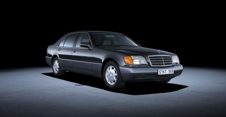
Pictured below is the beginning of this technology – the first car to use the CAN bus, the 1991 Mercedes-Benz W140.
To meet the increasing demand for efficient and reliable communication between electronic control units (ECUs), CAN Bus was designed as a lightweight yet robust networking solution.
Unlike traditional point-to-point wiring, which added complexity and weight to vehicles, CAN Bus introduced a streamlined method for ECUs to exchange data over a shared communication channel.
This architecture not only reduced wiring but also enhanced system reliability and fault tolerance. Its effectiveness in real-time communication quickly positioned CAN Bus as the industry standard, first in automotive applications and later in industrial automation, medical equipment, and other fields requiring high-speed, deterministic data exchange.
CAN Bus uses a differential signal transmission method with two dedicated lines: CAN High (CAN_H) and CAN Low (CAN_L). These two lines work in tandem to reduce noise and increase reliability. When a logical “0” (dominant bit) is transmitted, CAN_H goes to a higher voltage, and CAN_L drops to a lower voltage. When a logical “1” (recessive bit) is sent, both lines settle at the same voltage level.
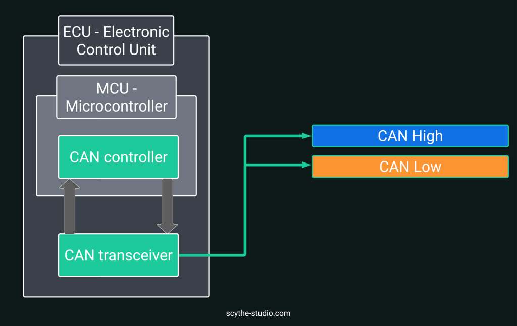
Let’s take a look at the construction of the previously mentioned Electronic Control Units (ECUs). An ECU consists of three main components:
Microcontroller (MCU): Processes CAN messages and executes control logic.
Inside MCU, there is an integrated CAN controller responsible for the logical processing of CAN Bus communication.
CAN Transceiver: Converts digital signals from the MCU into differential signals on the CAN bus and vice versa.
 Electronic Control Units ECU
ECUs communicate through CAN Bus by transmitting and receiving messages in the form of CAN frames, which follow a standardized structure.
A CAN Bus frame is a structured message used for communication between devices in a CAN network. It consists of several key fields. Here’s the structure of a standard CAN Bus data frame:
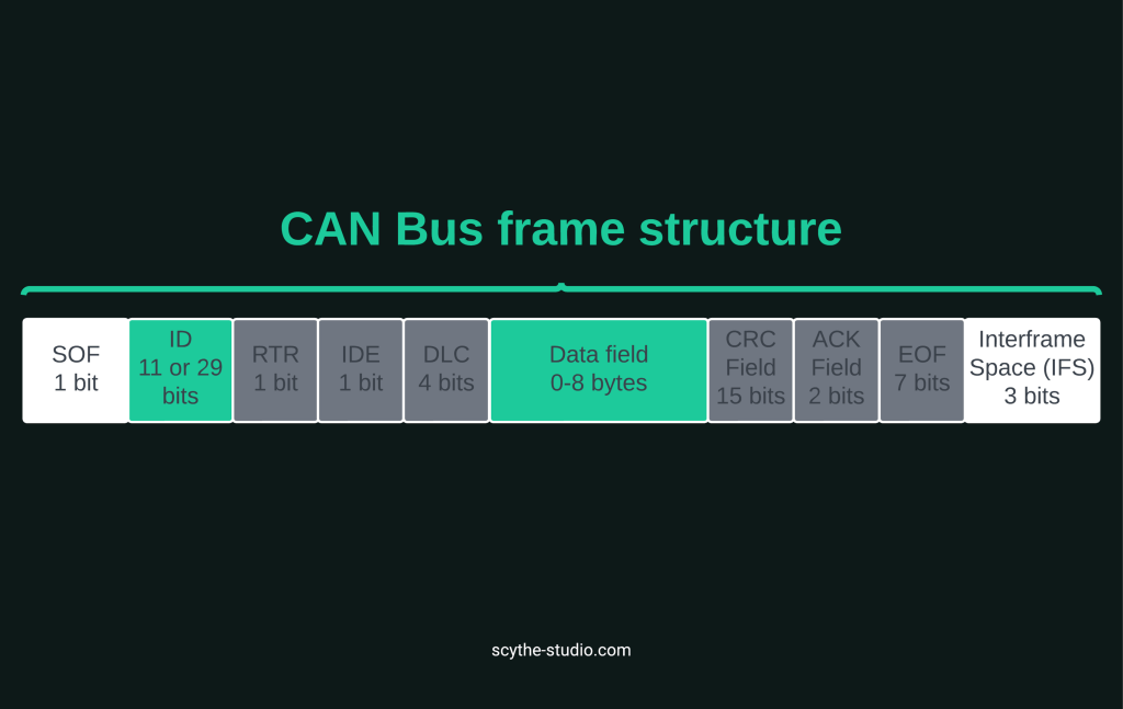 CAN Bus frame structure
The CAN Bus is a broadcast system, where all nodes receive every message but only process relevant ones. It does not use a global clock but relies on bit-level synchronization, where signal transitions keep nodes aligned.
To maintain stability, bit stuffing inserts an opposite bit after every five identical bits, ensuring proper synchronization. Arbitration prevents collisions—only the node with the lowest ID (highest priority) continues transmitting, while others stop immediately.
Nodes also use dynamic resynchronization, adjusting their timing when detecting unexpected transitions.
In the description of the frame structure I provided, some of the bits may have had different values depending on the version of the protocol used. The following presents the current versions of the protocol and what distinguishes them:
In addition to transmitting the information itself, we distinguish between several other frames in CAN. Their structure is the same, except that they differ in their purpose:
Automotive and Utility Vehicles – CAN Bus is a key communication system in modern vehicles, connecting electronic control units (ECUs) that manage the engine, transmission, ABS, airbags, climate control, and infotainment. It enables real-time diagnostics, reducing maintenance costs and improving vehicle efficiency.
Industrial Automation – In manufacturing and automation, CAN Bus connects machines, sensors, and controllers, ensuring the smooth operation of production lines and robotics. Its resistance to interference and high reliability make it ideal for demanding industrial environments.
Public Transport and Railways – CAN Bus is used in trains, trams, and buses to control traction, monitor vehicle health, manage passenger information systems, and automate doors, enhancing safety and efficiency.
Agriculture and Construction Machinery – Modern tractors, harvesters, and excavators rely on CAN Bus for engine management, hydraulics, and automation. It improves precision, reduces fuel consumption, and optimizes machine performance.
Medical Devices – CAN Bus is integrated into medical equipment like ventilators, infusion pumps, and imaging systems. It enables seamless communication between devices, ensuring accurate monitoring and patient safety.
Aerospace and Defense – Used in drones, aircraft, and military vehicles, CAN Bus supports avionics, autopilot systems, and diagnostics, ensuring reliability even in extreme conditions.
Energy and Smart Buildings – In energy management, CAN Bus helps monitor solar panels, wind turbines, and power grids. It also plays a role in smart buildings, controlling lighting, HVAC, and security systems for better efficiency.
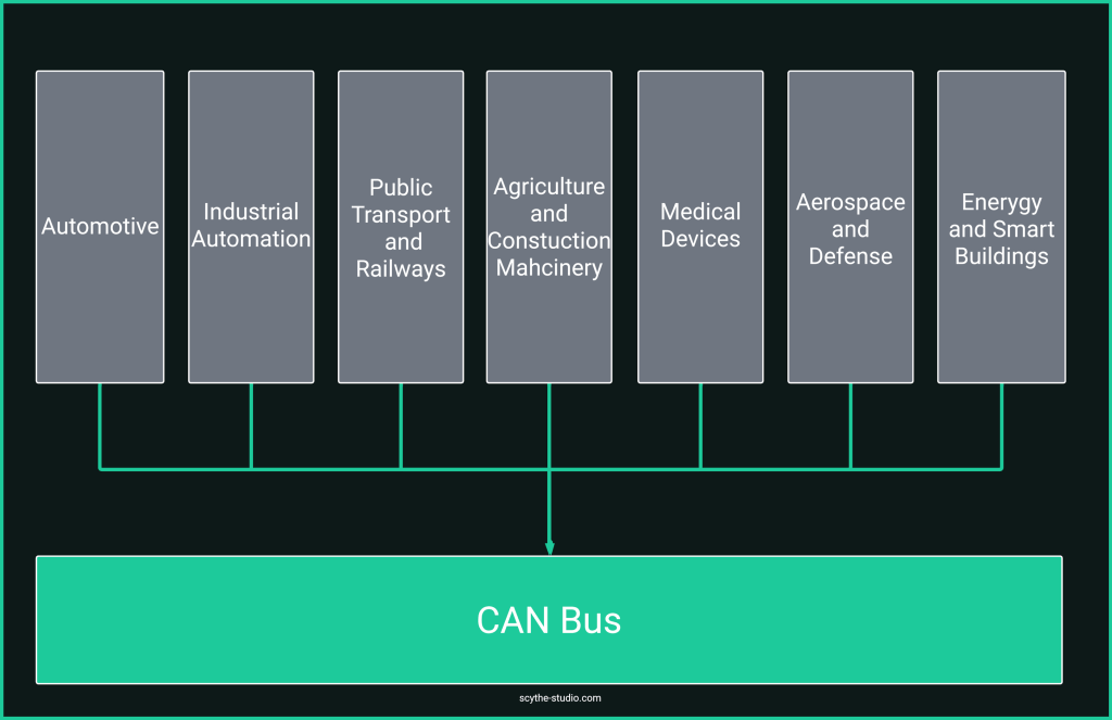 Industries using CAN Bus
Thanks to its versatility and robustness, CAN Bus remains a critical communication standard across multiple industries, from automotive to healthcare and beyond!
As a programmer working with embedded systems, I’ve found CAN Bus to be one of the most reliable and straightforward communication protocols out there—once you get past its quirks. Unlike RS-232 or RS-485, where you often end up dealing with point-to-point connections and extra wiring headaches, CAN Bus is a game-changer with its multi-node setup on just two wires.
Compared to Ethernet, CAN might feel a bit old-school with its lower data rates, but for real-time applications, it’s unbeatable. If you’re working on something like an ECU, where a delayed message could mean a car crash, CAN’s deterministic nature ensures that critical data gets through exactly when it should. Ethernet, on the other hand, is great for bulk data transfer but not ideal when every millisecond counts.
Then there’s LIN, which is like CAN’s simpler, cheaper cousin – fine for things like seat controls but not something I’d rely on for safety-critical systems.
As you may already know yourself, the Qt framework provides a number of libraries implementing communication formats. It is no different with CAN Bus. Within the Qt Serial Bus module, a set of classes is available to implement CAN Bus communication in your application.
Apart from the obvious advantages of using Qt in your project (yes, Qt development services is what Scythe does), there are 3 main advantages when using Qt Can Bus:
High-Level Abstraction – Qt provides an intuitive API for CAN communication, eliminating the need to interact directly with low-level drivers, file descriptors, or ioctl calls. Instead of manually managing CAN interfaces, you can use QCanBusDevice to establish connections and send/receive frames in a structured way. This makes your code cleaner, easier to maintain, and more portable. It also helps with changing between CAN Bus versions just by using can bus connection parameters.
Built-in CAN Bus Support—Qt natively supports multiple CAN backends, including SocketCAN (Linux), PeakCAN, and TinyCAN. This allows your application to work across different platforms with minimal modifications. For example, you can develop a testing tool on Linux using SocketCAN and then deploy the same application on Windows with PeakCAN by just switching the backend name. This flexibility makes Qt ideal for multi-platform development where hardware dependencies vary.
Efficient Event-Driven Model – Qt’s signal-slot mechanism is a perfect match for CAN communication, allowing your application to handle real-time messages asynchronously. Instead of constantly polling the bus for new data, your app can react automatically when a new frame arrives. For example, in a vehicle telemetry system, a signal could update a live speedometer whenever a new speed frame is received. Similarly, in an industrial automation setup, a CAN frame carrying temperature data could instantly trigger an alarm if values exceed a threshold, ensuring real-time responsiveness.

The Qt CAN Bus API provides a structured way to interact with CAN bus hardware. It includes several key classes:
Starting from Qt 6.5, additional classes were introduced to make CAN message handling even more efficient:
We’ve gone through all the planned theoretical parts, so it’s time for the practical demo. This time I decided to use some code from a previous blog post in which I made a parking sensor. If you haven’t read it yet, take a moment now to familiarise yourself with it. Only the UI will be used so don’t worry, it will be pretty straightforward.
The premise is. We have an app that connects to the parking sensor. This application, using GUI and sound signals, provides the user with information about the distance to the nearest obstacle. For a better understanding, take a look at our LinkedIn post, where we show this simple system in action.
Previously, we used an ultrasonic sensor attached to an ESP32 that communicated with the application via Bluetooth Low Energy. Unfortunately, the board I recently used does not have a CAN-Bus connector. I, therefore, decided to ‘simulate’ the hardware with a virtual can port and build in Linux tools for sending and retrieving CAN messages
If you’re developing with Qt and need a CAN bus for testing but don’t have physical hardware, Linux makes it easy to create a virtual CAN interface using SocketCAN. This allows you to test sending and receiving CAN frames without additional devices.
To set up a virtual CAN port, run the following commands in the terminal:
sudo modprobe vcan                    # Load the virtual CAN module
sudo ip link add dev vcan0 type vcan  # Create a virtual CAN interface named vcan0
sudo ip link set up vcan0             # Bring the virtual CAN interface online
Once the virtual CAN interface is running, you can use cansend and candump, two built-in tools for testing CAN communication:
candump vcan0 # Monitor all frames on vcan0
cansend vcan0 123#10 # Send frame with Id = 123 and payload 0x10
As far as the UI code is concerned it is the same as in the example with Bluetooth, the only difference is that instead of BLEController we now have CANBusController. So let’s take a look at what this class looks like
CANBusController::CANBusController(QObject *parent) :
    QObject(parent), m_device(nullptr)
{
    m_device = QCanBus::instance()->createDevice("socketcan", "vcan0");
    if (m_device) {
        connect(m_device, &QCanBusDevice::framesReceived, this, &CANBusController::processReceivedFrame);
    } else {
        qWarning() << "Cannot open CAN Bus interface, error" << m_device->errorString();
    }
}
void CANBusController::connectToCANBus() {
    if (m_device) {
        m_device->connectDevice();
    }
}
In the constructor, we create an instance of the QCanBusDevice object using the createDevice method. Here we provide two arguments, the name of the plugin and the name of the interface. Since we are using a virtual port, the plugin name is socketcan and the port name in our case is vcan0. If we want to test our application with a physical device, we just need to change the name of the plugin and the port and that’s it, Qt will do the rest for us! For connecting the device to the CAN Bus, we just need to call m_device->connectToDevice(). Now let’s take a look at processReceivedFrames method that handles all incoming frames.
void CANBusController::processReceivedFrame() {
    if (!m_device) return;

    while (m_device->framesAvailable()) {
        QCanBusFrame frame = m_device->readFrame();
        QCanBusFrame::FrameId frameId = frame.frameId();
        QByteArray payload = frame.payload();

        qDebug() << "ID: " << QString::number(frameId, 16).toUpper()
                 << " Data: " << payload.toHex().toUpper();

        if (frameId == DISTANCE_FRAME_ID && !payload.isEmpty()) {
            int distance = static_cast< uint8_t >(payload[0]);
            setDistance(distance);
        }
    }
}
This method is connected to the QCanBusDevice::FramesReceived signal. It is triggered every time it receives can bus frames. In our method, we first decode the received frame into id and payload and write the data to the console. then we check if the id is equal to the predefined constant. Such filtering can also be done by setting CAN bus connection parameters. For the purposes of this demo, however, I have left it in a simple form. Once we are sure that the frame has the correct frame ID, we decode its contents. CAN Bus data is usually stored in hexadecimal form so we do the appropriate transformations and call the setter to the `distance` variable.
As far as sending data is concerned, this is also very simple. Suppose we want to send an error frame where we have some error description as payload (string up to 8 chars). To do this, it is sufficient to do something like that:
void CANBusController::sendMessage(const QByteArray &data) {
    if (!m_device) return;

    if (data.size() > 8) {
        qWarning() << "Payload too large for CAN frame";
        return;
    }

    QCanBusFrame::FrameId frameId = ENGINE_MALFUNCTION_FRAME_ID;
    QCanBusFrame frame(frameId, data);

    if (!m_device->writeFrame(frame)) {
        qWarning() << "Failed to send frame";
    }
}
You can see how the application works below. Remember that the data sent and received is in hexadecimal (that's why when I am sending 100#10 it's setting the distance to 16 since 0x10(HEX) = 16(DEC).
To conclude with one more puzzle. When you click the send error button, a message is sent. Are you able to decode what its content is 🕵️♂️?
Feel free to have fun and enjoy reading the upcoming articles!
After reading this article, you probably recognize how important CAN Bus is as a technology. The example shown is, of course, very simple, and, in reality, projects using this form of communication are much more complex. If you need help implementing this solution in your project, do not hesitate to contact us and we will help you with any embedded software problem!


Let's face it? It is a challenge to get top Qt QML developers on board. Help yourself and start the collaboration with Scythe Studio - real experts in Qt C++ framework.
Discover our capabilitiesUsers of embedded devices – from industrial controllers to consumer electronics – are often unaware of hidden vulnerabilities that threaten […]
Graphical user interfaces (GUIs) are becoming more and more important in embedded devices – from home appliances to medical equipment […]
Technical managers in the embedded space often face a classic challenge: integrating industrial communication protocols into modern applications. One such […]
